Mechanical Actuators
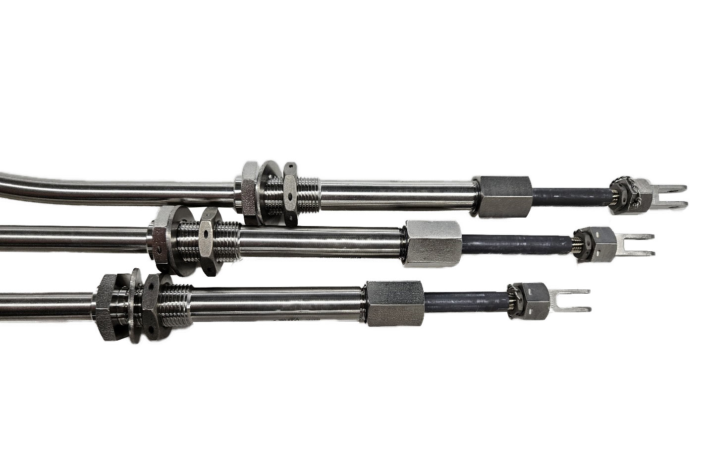
Ball Bearing Control Cables
AeroControlex ball bearing control cables are used in a wide variety of demanding applications. From throttle and flight controls on many commercial and military aircraft, to brake, landing gear, and gust lock controls on business jets. AeroControlex ball bearing controls are relied on daily to provide dependable and unmatched performance.
Characteristics
AeroControlex ball bearing controls are designed to be highly customizable to suit individual applications and custom configurations for stroke length, thread sizes, end fittings and the most rigorous environmental conditions. When required by the customers specific application, AeroControlex has a number of options to meet our customers most rigorous conditions including: 1) Seal Nut options, 2) Flexible or rigid casing, 3) a wide variety of protective covering, 4) a plethora of end fittings, swivel and end hardware to meet the custom needs of the end application while maximizing performance and reliability.
Typical Applications
- Flight Controls
- Throttle Controls
- Ram Air Turbine Controls
- Landing Gear & Brake Controls
- Emergency Controls
- Turbine Case Cooling Controls
- Engine and Fuel Controls
Product Features
- MIL-STD-810 and DO-160G Certified
-
Temperature range: -45° F to +450° F
(Options for high temperature applications of up to 800° F available) - Lubrication: Not Required
- Flexibility: Capable of multiple plane bends, up 900°F of total bends
- Load Efficiency: 90-98%
- Backlash/Lost Motion: as low as 0.030” (routing and load dependent)
- Maintenance Free
Standard Ball Bearing Cable Types
AeroControlex ball bearing controls are designed to be highly customizable to suit individual applications and custom configurations for stroke length, thread sizes, end fittings and the most rigorous environmental conditions. When required by the customers specific application, AeroControlex has a number of options to meet our customers most rigorous conditions including: 1) Seal Nut options, 2) Flexible or rigid casing, 3) a wide variety of protective covering, 4) a plethora of end fittings, swivel and end hardware to meet the custom needs of the end application while maximizing performance and reliability.
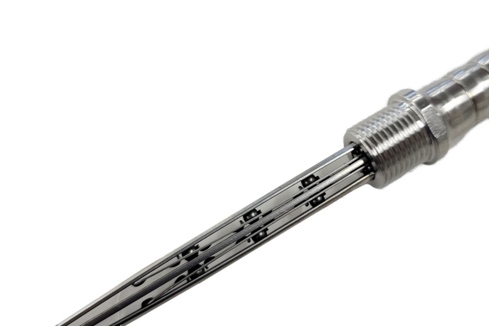
Typical Barrel Cam Type Control (315, 415, 515 and 615 series)
The Double Barrel Cam design features concentric inner and outer barrel cams, which are housed within the main sleeves and mechanically attached to the outer races. The cams are allowed to rotate as the outer races helix during installation, automatically offsetting the differences in arc radii. When the control is fully installed, these cams become self-locking, establishing both outer races as the reactive members of the control. The cam anchor design also prevents the possibility of stroke variation since the control is now permitted to bend around the center race. 715 series controls also available for Marine and ground defense applications for high load conditions upon request.
Typical Fixed-Sliding Anchor Type Control (410, 510 and 610 series)
For installations requiring the smallest envelope dimensions with less complex routings, the Fixed – Sliding Anchor design is also available. The Fixed – Sliding Anchor Control features one outer race which is securely anchored (the fixed race) and one which is allowed a limited degree of movement within the end fittings (the sliding race). This is accomplished by a slot at each end. Bend angle for this type of control is limited to one plane.
Design Guidelines
The basic specifications for each of the control series are defined on the accompanying capabilities chart. This chart shows the basic operational characteristics for each of the control series. Load carrying capability and bend radius are the distinguishing operating characteristics between series.
The standard configurations described on the following pages accommodate applications where input and/or output actions have straight push-pull motion. Where an arc articulation is required, a ball joint connector is recommended (See Accessories for selection). Rigid mounting of control cable end fittings is achieved with jam nuts and washers on the threaded portions of the main sleeves.
When required by a specific application, a number of options are available for sealing the control from the environment.
| Series | 300 | 400 | 500 | 600 |
|---|---|---|---|---|
| *Normal Duty: | 75 lbs. | 100 lbs. | 150 lbs. | 500 lbs. |
| *Limited Duty: | 150 lbs. | 200 lbs. | 300 lbs. | 1000 lbs. |
| Bend Radius | 6 in. 4 in. | 7 in. 4 in. | 7 in. 4 in. | 7 in. 4 in. |
| Weights | Approx. 0.14 lb/ft | Approx. 0.19 lb/ft | Approx. 0.31 lb/ft | Approx. 0.50 lb/ft |
| Temperature Range | Bare casing (M): -65 F to +450 F Vinyl covered casing (MV): -20 F to +350 F |
|||
| Lubrication | Not required | |||
| Flexibility | Multi-plane bends allowable | |||
| Test Requirements | MIL-C-7958, MIL-STD-810 | |||
| Efficiency | 90-98% | |||
| Materials | CRES (Stainless Steel) / Vinyl (covering) | |||
| Length (a) | Minimum 30 inches | |||
| Support Clamping | Recommended every 3 feet | |||
| Maintenance | None required | |||
| Shipping and Storage | Figure "8"(b) | |||
| *Loads Maximum recommended tension and compression (a) Lengths greater than 50 ft. will be supplied in (2) or more equal lengths with appropriate couplings. (b) Control cables are best shipped and stored in the figure "8" configuration received from the factory. This minimizes the possibility of damage. • Normal duty assumes a minimum product life of 100,000 cycles. • Rated compression loads are limited to 4 inch maximum stroke. • Duty cycles greater than 100,000 cycles can be achieved with increased bend radii on the control. |
||||