  |
|||||
| Design Overview
The flexibility of AeroControlex‘s ball bearing control is enabled
by several unique design features which allow the system to handle complex installations.
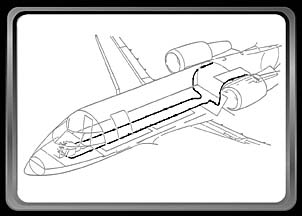
The flexibility, or bending angle, is defined by the relation of the end fittings to each other, not by the miscellaneous bends which might occur along the control cable’s installation route. For example, when the control cable is laid out
straight in one plane, and the end fittings directly oppose each other, the bend angle is
0ƒ. When the control cable is bent into a "U" configuration on that same plane,
and the end fittings face the same direction, the resultant angle is 180ƒ. However, if
that cable is bent again to form an "S" configuration, since the end fittings
directly oppose each other, the resultant effective AeroControlex ball bearing controls are recommended not to exceed 180 degrees of total bend. Therefore any number of bends can be accomplished during installation, as long as the difference between the total number of opposing bends does not exceed 180ƒ. This concept also applies to out of plane bends. The recommended distance between out of plane bends is a function of bend angle, bend radius, and load. Please contact us with specific requirements for your applications. |
|
||||
|
|||||
Typical Barrel Cam
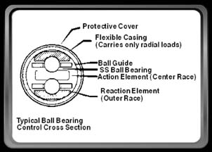
Type Control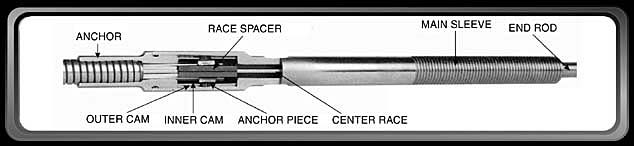 The Double Barrel Cam design features concentric inner and outer barrel cams which are housed within main sleeves and mechanically attached to the outer races. The cams are allowed to rotate as the outer races helix during installation, automatically offsetting the differences in arc radii. When the control is fully installed, these cams become self-locking, establishing both outer races as the reactive members of the control. The cam anchor design also prevents the possibility of stroke variation since the control is now permitted to bend around the center race. |
|||||
Typical Fixed-Sliding
Anchor Type Control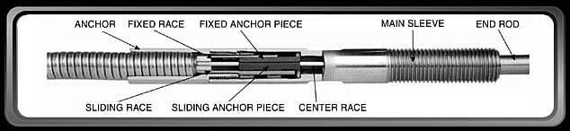 For installations requiring the smallest envelope dimensions with less complex routings, the Fixed - Sliding Anchor design is also available. These controls are designed as type 410, 510, and 610. The Fixed - Sliding Anchor Control features one outer race which is securely anchored (the fixed race) and one which is allowed a limited degree of movement within the end fittings (the sliding race). This is accomplished by a slot at each end. Bend angle for this type of control is limited to one direction |
|||||
|
|||||